
RoBusters| The Memory-Maker
Project Details
Awards & Nominations
RoBusters has received the following awards and nominations. Way to go!
The Challenge | The Memory-Maker
TECS (Tape with Embedded Compliant Switches)
Mechanical memory implementation with compliant mechanisms.
THE TEAM
We are RoΒusters, a team that consists of Mechanical Engineering students from the National Technical University of Athens.
THE CHALLENGE
Venus has a very hostile environment in which traditional electronics fail. So, in order to store data (temperarure, pressure, air speed, seismic activity, atmospheric and soil composition) from measurements taken, NASA suggests a mechanical memory to be used.
SOLUTION to the challenge "Memory-Maker"
There are many ways to store data with a mechanical system (vinyl type mechanisms) but, our solution to the problem is radical. We use compliant mechanisms to make 2-stage switches and "reinvent" the bit. That way we are able to store raw data and compress them. However, the greatest features are the fact that TECS is rewritable, can easily withstand 450°C and it is suitable for working on sulfuric acid environments, as the number of moving parts is very limited compared to other setups.
IMPACT
The majority of missions on Venus surface have not been successful, so the information on this planet known to us are very limited. The reason these data are so valuable, is that, understanding the outer world does not just answer an ancient question. It motivates us to develop new technologies, useful not only for space exploration, but also for missions on Earth's most hostile places. Volcanoes & Earth's mantle, trenches and high altitude expeditions are some applications in which a robust and reliable memory storage system could be handy, lowering the mission's cost (less insulation needed) and increasing its reliability. Αll in an effort to solve problems that make humanity suffocate (climate change - energy crisis). Whats-more, being independent from sensitive electronic devices might be extremely useful in urgent situations where our civilization's vital information might need to be stored safely from radiation or other damaging conditions. Because by exploring others, we learn more about ourselves.
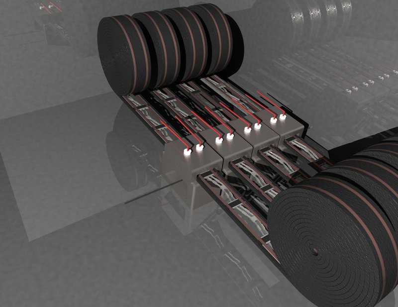
"TECS" - Tape with Embedded Compliant Switches
It is essentially a very long tape, on which the switches are attached in series, each one representing a "bit" of information. The switches are single-part(monolithic) compliant mechanisms, and can be bistable, tristable, quadristable, multi-stable, depending on the numeral system we want the setup to be modelled on. On the binary approach of TECS, the "write" and "erase" functions are accomplished mechanically by affecting the position of the switch, while the "read" process electrically, so that the information remains unaltered. The four reading probes are responsible for reading the corresponding current across the grounded bottom of the strip and the tip of the probe. Each probe is connected to a different resistance depending on the position of the compliant switch. The layout is smartly compact; rolled tape and small enough switches, so that in 1x1x0.25 [m], information of 1MB (0.8 MB ~ 1.2 MB) can be stored.Furthermore, the memory will be enclosed inside a casing with high heat and pressure capacity, especially designed for smoothening the rapid transient thermodynamic changes (Earth-Space/Space-Venus), to prevent the violent phase change of trapped air(bubbles which lead to rapid expansion and potential destruction of the assembly) during manufacturing and also retain any wanted tolerances by reducing thermal dilatation.
About Compliant Mechanisms
Flexible mechanisms that rely on elastic body deformation in order to be able to return an output (force, displacement) at a given input (force, displacement). Their great advantage is that they consist of very few parts, if not of a single one, and can be printed even on the micron scale.
Dynamics of compliant mechanisms-Material Selection-Trade off
In order to make the mechanism work, it needs to be made of materials that have electrical conductivity, have resistance to sulfuric acid, keep their elastic behavior within limits and do not expand uncontrollably in the 450°C range. We have come to a conclusion, to use iron-silicone alloys (siguss), nickel-based alloys (inconel) or gold-plated titanium. All of the above alloys include inert metals to oxidizing acids, and the overall thermal expansion at 450°C is not significant enough to cause failure in the specific design of the compliant mechanism. The trade here is the actual size of the mechanism in order to be manufactured from one of these materials.
Tape-Material selection-Trade off
In order to successfully create an "elastic" tape with some embedded conductive wires, we have concluded that we should split it in as many parts as the number of switches. The materials will be similar to the ones already mentioned, with some elastomers, polymers, or sheet-metal addition.
FUTURE
Further development of our idea, in order to store more data in the future, would include the implementation of some basic compression of the binary data (11100000->1110x) via a mechanical controller and the design of tri/quadri/multi-stable switches to reduce the number of bits needed to store a byte of information (and as a result the number of switches).
Material Selection table
Materials for Compliant Switches/Properties | Yield Strength at 400oC(MPa) | Modulus of Elasticity (GPa) | Linear Thermal Expansion Coeff. (10-6/oK) | Melting Point (oC) | Oxidation Resistance |
Silicon-Iron Alloys (Siguss) | - | - | - | 1200-1300oC | High resistance to oxidation and corrosion from H2SO4 |
Inconel 600 | 203 | 207 | 14.2 | 1370-1425oC | Reacts with hot sulfuric acid after reaching 1149oC. |
Ti-6Al-4V | 900 | 110 | 9.7 | 1604-1660oC | Rapid oxidation at ~ 500oC |
Zirconium | 230 | 94.5 | 6.2 | 1852oC | High resistance to oxidation and acid corrosion |
Platinum | 200 | 168 | 8.8 | 1768oC | Oxidation starts occurring at 500oC and it does react with acids |
Compliant switch kinematics
Early design of a bistable compliant mechanism
We modeled the bistable compliant switch as a buckled beam that is in a stable state. The equation that describes its shape is:
h/2*(1-cos(2*pi*x/l))
Where x is the axial dimension, l is the buckled length of the beam and h is the displacement of the beam.
The kinematic equation of the beam is given by the following equation:
F = (E*h*I/l^3)*((3*pi^4*Q^2/)/2)*T*[(T-3)^2+((4/3*Q^2)-1/4)]
Where:
E: modulus of elasticity of the compliant switch material
I: moment of inertia of the beam’s cross section
T: normalized deformation
W: width of the beam
B: height of the beam
Q: geometry factor h/w
Proposed designs for manufacture:

1st Design:
- W = 0.2mm
- H = 0.45mm
- L = 7.5mm
- B = 1.5mm
- E = 2.5 GPa
Necessary force F = 1.03 N

2nd Design:
- W = 0.25mm
- H = 1mm
- L = 10mm
- B = 1mm
- E = 2 GPa
Necessary force F = 1.01 N
So we can see that for a scaled down version of the above cases, the actuation forces can be significantly smaller.
Working prototype-proof of concept
- our working prototype tape(Image 1):Aluminum foil represents the conductive areas of the tape.
- The switches are also conductive in such a way that they close a specific circuit according to their state.Each state circuit is connected to different resistor(reading function) thus two different voltages are read between the grounded bottom and the positive probe.(image 2)When the led is lit it reads "1" and when led is off it reads "0".(Electrical output)
- the switch is not optimized, but this first brute force approach also works for our proof of concept(image 3)

Image 1

image 2
![[video-to-gif output image]](https://im2.ezgif.com/tmp/ezgif-2-3baf515a9111.gif)
Image 3
Extra links
- https://drive.google.com/drive/folders/1Vjb6pGBefa...(Contains a working prototype we constructed)
sources:
- https://www.nasa.gov/feature/automaton-rover-for-e...
- https://www.nasa.gov/sites/default/files/atoms/fil...
- https://www.researchgate.net/publication/322321879...