
Signal Life| Internet on the Ocean
Project Details
Awards & Nominations
Signal Life has received the following awards and nominations. Way to go!
The Challenge | Internet on the Ocean
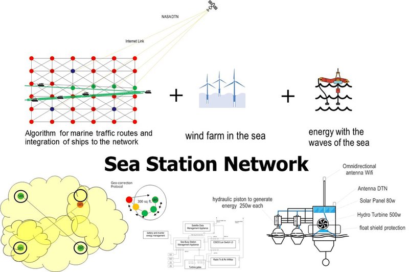
Mobile and Floating Sea Station Network for Internet Ocean
Sea Station Network (SeSNet) - Internet in the ocean at 65 square miles with 36 electrically self-supporting marine movable floating stations with NASA DTN with geocorrection, WiFi, WiMax, IGRP, OSPF, NTP protocol.
Need and Demand
Far from imagining that there is no great demand for internet services on the ocean, since we do not travel most of the sea or we do not spend much of our time in the ocean, coupled with the fact that there are currently many areas in the different continents where the internet does not arrive, it would lead us to conclude its null feasibility or bad investment the implementation of internet infrastructure on the ocean. However, there are data such as MarineTraffic.com shows the position of virtually every commercial naval vessel in the world (800 million positions per month). In addition to being visually impressive, the map is an interesting way to visualize the flow of people and goods around the world: where the hot spots are and where they are not.Ships are color coded by type:

Figure 1.- Map of the Day: All the World’s Maritime Traffic
Green = Cargo Ship
Red = Tanker
Purple = Pleasure Vessel
Blue = Passenger Vessel
Cyan = Tug or Special Vessel
Orange = Fishing
Applicability
The applications of our proposed solution to the challenge of internet in the ocean are:
1.- We will provide internet to users within a 12-mile radius through floating stations at sea similar to marine buoys, a hydraulic generator based on the movement of sea waves will be included, in addition to an array of solar cells, the communication for the users will be via WiMax, a buoy network will be formed that also their way of extending the network will be with the use of WiMax.

2.- Use the NASA Suite protocol called DTN to know the status of the stations, send data in a special channel for measurements and instrumentation, as well as warning signs of navigations or weather conditions in the area of the buoys.

3.- The maritime stations of the buoys will be floating, with a counterweight that prevents them from being turned over, however if they could be moved by the waves, for this they will have a set of water outlet gates that moved the turbines through 4-axis with which we will seek to simulate the momentum of a boat to correct the position, the latter will be sent by the DTN protocol.
4.- The buoys will have an application to control their position in a radius of 300 square feet, after leaving this area, a signal will be sent through the DTN to correct their position and remain in this state until it is within the allowed area, additionally it will communicate with the neighboring nodes to indicate the error of the buoy and they themselves will send the error to the buoy that is outside their area.

5.- The DTN protocol will help us to optimize the movement of buoys with the idea of improving traffic routes and transit schedules of the ships, with defined limits to avoid the accumulation of buoys.

6.- It is considered the development of a mobile and web application for the use of station information, such as 911, compass and orientation to reach the next buoy to increase its reception power, know its position through triangulation and history of Buoys route where I reach registration, this for emergencies or shipwrecks.
7.- Our complementary elements to integrate theSeSNet are the current maritime projects, such as oil, wind stations at sea,tidal stations, private, commercial and passenger ships, the project includesincluding them and enhancing the use of the proposed technologies plus theirfuture updates.

Objectives to responder Energy
The issue of energy is a complication for the station because we need power to maintain communications equipment, Wimax transmitters, processing and measurement sensors. NetworkExtending the Wi-Fi or Wimax networkWe need the communication to users who are within a radius of 12 thousand to be able to provide the internet service via Wimax technology.
A mesh type network must be created that can support the loss of one or more nodes and that allows data traffic. Internet linksWe must have a satellite connection to exit the Internet service of the entire network and usersconnected, you can analyze alternatives to internet links which will depend on their implementation according to the existing infrastructure conventions on the coasts.
Integration of the NASA DTN protocol suiteExploit the Delay/Disruption Tolerant Networking (DTN) protocol suite to control the position of the marine buoy stations (MbS), manage and optimize the positions of the MbS for a better connection of the users, to know the status of the MbS, dispatch of algae and marine emergencies with impact in humans, atmospheric conditions, instrumentation channel and specialized measurements. Instrumentation and measurementsWe need a microprocessor that can integrate earthquake sensors, sea wave motion, temperature, marine sound (optional), handle an application to manage battery power, seawater outlets after they pass through the turbine through of gate management, processing and making decisions based on information from the NASA DTN, position data received from GPS and time synchronization.
Solution
The solution is to build floating marine stations with wireless communication systemscapable of propagating and expanding the Wifi or WiMax network to users or
applications within a radius of 12 square miles per node, each station must be
self-supported in its power generation by hydraulic and solar means, then each
station will be a network node that we will call Sea Buoy Station (SBS).
When floating, they will have a form of navigation taking advantage of the expulsion
of seawater that comes out of the turbine, thereby correcting their position within
a defined and assigned range.
Each station will have a way to connect and register users, with the Access Bouy Station (ABS) application, this to intersperse the use of available technologies such as DTN, WiFi or WiMax, for users, applications, devices or sensors. The network will be called SeSNet which is scalable by the number of SBS nodes and compatible to integrate different technologies already existing at sea.
Network
For communication between the nodes via WiMax, the TCP / IP, IGRP, OSPF protocols will be enabled, such as node discovery protocols, cost management for cases of dropped nodes and time optimization and latency reduction, as well as protocols forsynchronization of NTP time.We will provide internet to users within a 12-mile radius through floating stations at sea similar to marine buoys, a hydraulic generator based on the movement of sea waves will be included, in addition to an array of solar cells, the communication for the users will be via WiMax, a buoy network will be formed that also their way of extending the network will be with the use of WiMax.
Use the NASA Suite protocol called DTN to know thestatus of the stations, send data in a special channel for measurements andinstrumentation, as well as warning signs of navigations or weather conditionsin the area of the buoys.The maritime stations of the buoys will be floating, with a counterweight that prevents them from being turned over, however if they could be moved by the waves, for this they will have a set of water outlet gates that moved the turbines through 4-axis with which we will seek to simulate the momentum of a boat to correct the position, the latter will be sent by the DTN protocol.
Use the NASA Suite protocol called DTN to know the status of the stations, send data in a special channel for measurements and instrumentation, as well as warning signs of navigations or weather conditions in the area of the buoys.
The DTN protocol will help us to optimize the movement of buoys with the idea of improving traffic routes and transit schedules of the ships, with defined limits to avoid the accumulation of buoys.
The buoys will have an application to control their position in a radius of 300 square feet, after leaving this area, a signal willbe sent through the DTN to correct their position and remain in this stateuntil it is within the allowed area, additionally it will communicate with theneighboring nodes to indicate the error of the buoy and they themselves willsend the error to the buoy that is outside their area.Internet linksWe must have a satellite connection to exit the Internet service of the entire network and usersconnected, you can analyze alternatives to internet links which will depend on their implementation according to the existing infrastructure conventions on the coasts.
Because we need at least 400 watts of maximum power from our radio for WiMax transmission, plus the communication equipment for the data network approximately 60 watts and the data processing and instrumentation equipment we would be talking at a maximum power of 460 watts.
To solve this need for energy we will be generating energy through the waves of the sea with two pistons connected to a water turbine, pushing the seawater towards the turbine, with this movement we are calculating to generate 500 watts, additionally 4 solar panels will be installed with a maximum generation of 80 watts, this to leave a remnant of energy, for battery charging through the energy managersystem and the intelligent inverter
The DTN protocol will help us to optimize the movementof buoys with the idea of improving traffic routes and transit schedules of theships, with defined limits to avoid the accumulation of buoys.It is considered the development of a mobile and web application for the use of station information, such as 911, compass and orientation to reach the next buoy to increase its reception power, know its position through triangulation and history of Buoys route where I reach registration, this for emergencies or shipwrecks.
Our complementary elements to integrate the SeSNetare the current maritime projects, such as oil, wind stations at sea, tidalstations, private, commercial and passenger ships, the project includesincluding them and enhancing the use of the proposed technologies plus theirfuture updates.
Hardware:
Pelton Turbines
The proposal we consider a Pelton Turbines, they are known as pressure turbines, using 500W.
The force of the water impulse is responsible for the rotation of the turbine.Measurements: 19.68in x 11.02in x 8.66in
1. With the best permanent magnet NdFeB, high quality pure copper winding, the product can generate stable and high efficiency power generator.
2.Specially designed rotor and rotation, low resistancemoment in start-up, good in cooling
3. Gear, direct transmission, and low permanent rare earth magnet generator, easy and safe for operation and maintenance
.4. Die casting alluminum alloy case, anti-corrosion, acid and alkali resistant, anti salt corrosionIt must run at 3600 RPM for 60 hertz or 3000 RPM for 50 hertz.
Looking for the best positions within the station and the place that best takes advantage of sunlight, an arrangement equivalent to 80 watts of power would be placed for the Solar panels.
Solar Panel
Epcom PRO5012, 50 Watts for 12 Volts systemMaximum Power: 50WVoltage: 18VOpen circuit voltage (Voc) 22.2 VShort circuit current (Isc) 3.96 AAmbient temperature -40 to 80 ° CMaximum system voltage 600 V2.08in x 2.59in x 0.09in.
Energy
Because we need at least 400 watts of maximum power from our radio for WiMax transmission, plus the communication equipment for the data network approximately 60 watts and the data processing and instrumentation equipment we would be talking at a maximum power of 460 watts.
To solve this need for energy we will be generating energy through the waves of the sea with two pistons connected to a water turbine, pushing the seawater towards the turbine, with this movement we are calculating to generate 500 watts, additionally 4 solar panels will be installed with a maximum generation of 80 watts, this to leave a remnant of energy, for battery charging through the energy manager system and the intelligent inverter.

On the issue of heat generation of communications and data devices, to reduce the internal temperature we will install a ventilation system and an aluminum heatsink attached to the chassis taking advantage of the outside temperature to reduce it by means of heat transfer and external cooling.

Figure.- fan and heatsink system attached to the station chassis for better internal heat dissipation
Micro Computer model Intel NUC NUC8i7BEKGet ready for spectacularly responsive performance from the Intel® NUC with 8th Generation Intel® Core™ i7 processor. The latest generation Intel NUC kit lets you or your customers build the exact system they want. From choosing memory options to storage configurations, the benefit of building up an Intel NUC kit is the ability to completely customize the kit for a specific usage. Whether editing 4K video, casual gaming, or serious multitasking, the Intel® NUC8i7BEH Mini PC kit delivers the features people want—in a size that fits easily into any lifestyle and any room in the house. The First Intel® NUC Kit with a Quad-core 8th Generation Intel® Core™ i7 Processor.
The Intel NUC8i7BEH Mini PC kit with a true quad-core 8th Generation Intel® Core™ i7 processor delivers a big jump in performance compared to the previous generation Intel® NUC7i7BNH. Whether it’s built to create video content or mega task, the Intel NUC8i7BEH Mini PC kit gives great visual immersion with Iris® Plus graphics 655 and the unprecedented performance of Intel® Core™ processors.

LAN Switch Layer 3
For communication between the nodes via WiMax, the TCP / IP, IGRP, OSPF protocols will be enabled, such as node discovery protocols, cost management for cases of dropped nodes and time optimization and latency reduction, as well as protocols for synchronization of NTP time. The proposed solution due to the amount of data, users and information transfer and given that the internet connection will be limited by satellite bandwidth, we believe that a Cisco 200 Series Cisco router router equipment could be optimal. Build a Powerful, Easy-to-Use Basic.
The key to succeeding in today’s competitive business environment is investing resources wisely – knowing how to separate the essential from the extraneous and get the most value for your dollar. As the backbone of your business and productivity applications, the small business network clearly falls into the “essential” category. But that doesn’t mean you need the most advanced feature set on the market.

With Cisco® 200 Series Smart Switches, you can achieve business-class network security and performance without paying for advanced network management features that you will not need. When you need a reliable solution to share network resources and connect computers, printers, and servers, but low cost is a top priority, Cisco 200 Series Smart Switches provide the ideal solution.
An energy-efficient solution: Cisco 200 Series switches are designed to be energy efficient and eco-friendly without compromising performance. They help conserve energy by optimizing power use, which helps protect the environment and lowers your energy costs. Power-saving features include:
◦ Energy-Efficient Ethernet (EEE, the IEEE 802.3az standard), supported on Cisco 200 Series Gigabit Ethernet switch models. EEE improves the efficiency of network equipment and provides standardized signaling mechanisms that can enable rapid transitions between normal operation and low power idle (LPI) states in systems on either end of the physical layer link.
◦ Automatic power down on Gigabit Ethernet ports when a link is not active.
◦ Embedded intelligence to adjust power based on cable length on Gigabit Ethernet models.
◦ Fanless design in most models, which reduces power consumption, increases reliability, and provides quieter operation.
Radio Tx & Rx WiMax
To extend the WiFi signal and the connections to the users of the internet service, the proposal is to use WiMax technology with which coverage of up to 30 miles can be had, in our case for power, investment and return costs, We will use a technology that allows us a range of up to 12 miles with maximum 17 miles, using an omnidirectional antenna to try to radiate a better area.

Figure.- Block diagram of the WiMax base station equipment.
The solution is through a Air4G employs software defined radio (SDR) technology, together with two transmit paths and four receive paths, antennas and GPS receiver all in a highly integrated, physically small and light, all outdoor package. Air4G has been designed and optimized for the 700 MHz, 2.3, 2.5 and 3.3-3.8 GHz Mobile WiMAX/LTE bands. The product has been designed to address the markets needs by supporting the current and future air interfaces thanks to its SDR technology. When running mobile WiMAX, Air4G supports 3.5, 7 and 10MHz channel sises.
Air4G is a highly integrated compact, yet powerful, base station with all-in-one packaging of RF and base-band components. It is available as an all outdoor solution for Mobile WiMAX and LTE applications to minimize physical footprint and operator OPEX. It saves the need for an air conditioned shelter (which is required in other architectures such as split indoor/outdoor architectures). Air4G complements Pico Base Stations like AirSynergy (and naturally has much higher Tx power and much better link budget).
Thanks to the efficient power amplifier technology employed in its RF implementation, Air4G implements dual 40dBm (10W) transmitters in 2.X GHz and dual 37 dBm (5W) transmitters in 3.X GHz band.
The latter being a great advantage, because typically the consumption of WiMax stations or bases required up to 600 watts, with these total consumptions of station we would need approximately 380 watts
Appliance and Apps
Satellite Data Management Appliance (SDMA)
The DTN protocol suite will be managed through a mirco computer called Satellite Data Management Appliancewith the processing, storage and performance capacity necessary to install the linux or unix operating system, mount the DTN suite, function as an outbound proxy for satellite internet connection, functions positioning through a dedicated port with GPS, establish a dedicated channel for sending measurements and instrumentation of the station sensors, compatible with survival mode functionality for cases of neighboring equipment failures and initiate ways to recover the system automatically through processes, tasks and condition banners self managing processes (PROCMaster).

Figure 6.- Sea Buoy Station Hardware for Communication and Data Link.
Sea Buoy Station Management Appliance (SeBSMA)
Similar to the SDSA, it will be installed in a microcomputer with at least 4 ports for instrumentation of the station sensors, process and send the information through a tcp / ip ethernet port connected to the LAN Switch, with the linux or unix operating system, it will have Mounted the application for battery power management and through a writing port will control the turbine's output gates, which are referred to geo positions.
Network and Integrate NASA DTN Suite protocol
Delay/Disruption Tolerant Networking (DTN) We consider the use of Delay/Disruption Tolerant Networking (DTN) because it is designed to extends the terrestrial Internet capabilities into the challenging communication environments in space where the conventional Internet does not work well. These environments are typically subject to frequent disruptions, links that are limited to one direction, possibly long delays and high error rates.
The DTN as a protocol suite also contains network management, security, routing and quality-of-service capabilities, which are similar to the capabilities provided by the terrestrial Internet suite, Its application in our project is excellent to overcome extreme environmental conditions, curvature of the earth, low antennas, the main use would be the following:
1.- Communication between marine buoy stations with satellites to know the health of the station
.2.- Positioning of stations to optimize the distribution of the Wi-Fi signal.
3.- Communication for disasters (tsunamis, earthquakes, storms, high waves) and emergencies (shipwreck alert, distress or rescue signal).
4.- Establish a dedicated channel for sending measurements and instrumentation of the station sensors. The DTN protocol suite can operate in tandem with the terrestrial IP suite or it can operate independently. DTN provides assured delivery of data using automatic store-and-forward mechanisms. Each data packet that is received is forwarded immediately if possible, but stored for future transmission if forwarding is not currently possible but is expected to be possible in the future. As a result, only the next hop needs to be available when using DTN.
Internet links
As shown in Sea Buoy Station Hardware for Communication and Data Link, the solution considers using a satellite data communication as an outbound link to the Internet, functioning as a gateway of the SeSNet network in a virtual architecture of Satellite HUB, for the solution an area of 65 miles was considered, needing 36 stations, for this network we would occupy at least 4 internet links, that is, 4 stations would function as a gateway with satellite data connection, they would be placed so that a maximum of 4 hops are required to have internet access in normal state of the network, in case of problems there would be one or two more jumps.
Being at least 4 links reduces the need for more links per user, that is, if they navigate through this area of 65 miles at least 800 ships, perhaps 750 require satellite internet links to perform their functions, in this case it would be provided by 4 links, this will depend on each zone. Instrumentation and measurements to create the dedicated channel for instrumentation and measurements of the station, 3 sensors for earthquake measurements, temperature and sea wave size will be installed at least, the selected sensors will be adapted and next to the buoy for use in extreme conditions, especially by The salinity will be read by the APP which will process the information and send it to the APP in the form of dedicated packages and applications for sending to remote databases, which will be available for consumption through web services.
For the bandwidth to be used it will be based on the number of possible subscribers calculated with the maritime traffic algorithm (MaTra) and a minimum base bandwidth, with this the use of bandwidth would be dynamic, for example for a relationship of 20 to 40 subscribers for 1 Mbps, knowing that they are mobile users, the MaTra should adjust the bandwidths to optimize connections and improve internet services accompanied by the application of QoS.
Disadvantages to be resolved and next steps
Some of the questions and challenges to improve or answer related to our proposal would be:
1.- Improve the buoy anchor system, achieve a balance of weight to withstand extreme conditions.
2.- Improve the position control system by means of the floodgates and the water outlet in the form of propulsion or take advantage of the excess energy to install a motor-type motor control that allows mobility at sea to be improved.
3.- Improve WiMax technologies for greater coverage in square miles and thus require fewer nodes
.4.- Explore alternatives and evaluate coastal connections with repeaters as the last node, fiber optic cables added to the first station.
5.- Develop a standard that allows the compatibility of WiMax, WiFi, 4G, 5G, DTN technologies adaptively to the environment.
Conclusion
The inclusion and development of a network architecture that considers the use of existing technologies in the ocean such as wind farms, energies with the sea, oil stations, ships and coastal repeaters, all of them as network elements, this together with the SeSNet project create a network that leverages and shares its resources to optimize costs.Develop a standard that allows the compatibility of WiMax, WiFi, 4G, 5G, DTN technologies adaptively to the environment.In conclusion the benefits that can be achieved with the development of a project like this:
1.- Reduce the cost of internet access, instead of each user having the need to hire the service to share.
2.- The principle of network has always been to seek to share resources, making use and approval efficient, so creating a network in the topology and technologies that is selected can always be better than the current form.
3.- The creation of infrastructure in the ocean is a way to encourage new fields of action that are currently low developed, learn more about the oceans, develop new jobs and needs from exploration.
4.- Transform these data and information into knowledge and power to improve the present human life, leaving the bases for the following generations.
Thanksa lot for this experience!
Sincerelythe Signal Life Team
Signal Life Final Report
Resources:
https://www.nasa.gov/content/dtn
WiMax power consumition
https://pdfs.semanticscholar.org/6202/eb08bc74741d8d481f7b75731e1f51ced9b3.pdf
Map of one day maritime traffic
https://thesoundingline.com/map-day-worlds-shipping-traffic/
https://www.marinetraffic.com/en/ais/home/centerx:-12.1/centery:24.8/zoom:2
WiMax Radio
https://www.winncom.com/pdf/Airspan_Air4g_W24/Airspan_Air4G_Brochure_070111.pdf
Cisco Serie 200 Spec
Intel® NUC Kit with a Quad-core 8th Generation Intel® Core™ i7 Processor
https://www.intel.la/content/www/xl/es/products/do...
Smart Inverter
http://iea- pvps.org/fileadmin/html/img/21_Grid_integration_with_modern_PV_inverters__Andre_Luthi__Sputnik_engineering_AG_.pdf