
Stars's five| The Memory-Maker
Project Details
The Challenge | The Memory-Maker
Spider_Venus
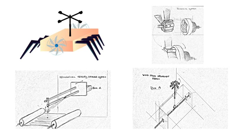
A mechanical solution for storing data using a drilling head to pierce a suitably chosen fireproof fabric; and a piezoelectric material used to activate a servo-motor for changing the direction of the wind turbines and so the rover march.
1. Considerations about the operating conditions
Following a study of the data in our possession and made available by the NASA database (https://solarsystem.nasa.gov/planets/venus/overview/) the following critical issues emerged for the design and development of a solution stable:
- Surface temperature between 380 ° C - 450 ° C
Such a high surface temperature prevents optimal performance for a very high number of materials which therefore become difficult to use and / or control;
- Atmospheric pressure of around 92 ATMs
Venus pressure is about 92 times the Earth's atmospheric pressure. This can lead to problems with the locomotion of the rover or the performance of its internal components.
- Sulfuric acid clouds
They contribute to raising the temperature and can lead to wear or even the dissolution of different materials, especially downstream of possible precipitation.
- Greenhouse effect
The greenhouse effect is mainly generated by the conjunction of two factors: thick clouds of sulfuric acid (which prevent regular filtering of sunlight) and atmospheric composition (which sees 97% as a dominant component of CO2). The greenhouse effect thus contributes to making the planet even warmer and brings it to temperatures even higher than that of Mercury.
- Atmosphere
The Venusian atmosphere is much denser than the terrestrial one and therefore involves a high temperature rise during the landing of the probe on the planet.
2. State of art: AREE NASA CONCEPT
https://www.youtube.com/watch?v=VU51JY6DWlE
https://www.nasa.gov/feature/automaton-rover-for-extreme-environments-aree/
https://www.youtube.com/watch?v=Tn4BTSTTCNI
Automata could be the key for unlocking the secrets for some of the most extreme environments in the solar system such as the surface of Venus. AREE, the Automaton Rover for Extreme Environments replaces vulnerable electronics with an entirely mechanical design. By utilizing high temperature alloys, the rover would survive for weeks if not months, allowing it to collect and return valuable long term longitudinal science data from the surface of Venus. The solution The solution below wants to be an approximation of an electromechanical system with low-voltage electric components like AREE project’s mechanics.
Communicating the data back to earth is the most challenging aspect of the system design but multiple options are open for study including a retroreflector, a simple electronic high temperature transponder, or inscribing phonograph style records to be launched via a balloon to a high altitude drone capable of transmitting the data back to Earth.
3. Proposed solutions
3.1 Mechanical memory storage device
We intend to design a mechanical storage system that makes use of materials resistant to temperatures between 380 ° and 450 ° Celsius, in order to store 1 MB of information. The dimensions want to be such as to allow the system to fit into a 25x100x100 box and, even with a careful choice of the involved materials, to not exceed a total mass of 25Kg. As for pressure and possible problems related to precipitations, our challenge falls outside the study of a solution that takes it into account.
3.1.1 Feasibility study
A surface temperature between 380 °C and 450 °C, in the absence of sunlight, entails an equivalent thermal level inside the rover, which is why the technology we want to design must be able to work at temperatures equal to the one on the surface, without compromising in any way the reliability of the measurement.
Assuming that the probe can record real values in a suitable scale of representation, calibrated according to the quantity subject to measurement, we first of all calculated how many measurements we can do in order to approximate 1MB of information. Having to work on a system that could be useful for wind and temperature measurements, we hypothesized a conversion from real to binary, expressed in a floating point standard. It is therefore calculated that on 32 bits (necessary to represent the single real value), the values that can be recorded are around 250,000 (1MB is about 8,000,000 bits => 8,000,000 / 32 = 250,000) to be divided equally between the quantities under consideration. To address this point, we wanted to use a flat writing surface.
In order to find a useful surface for the cause, metallic and ceramic materials of different nature were then evaluated and studied. Ceramic materials have been discarded because, being non-flexible, they involve excessive volumetric expenditure. In fact, the need to store 1MB requires, on the basis of the chosen coding system, the use of a useful writing area of approximately 315m ^ 2 (in the case of a physical distance between two successive samplings equal to 0.5 cm) . Similarly, metals were discarded because they were either too heavy or excessively sensitive to temperature changes.
The need to insert the device in a maximum space of 25x100x100 cm (where the writing instruments should also reside) led us to evaluate a system of rollers, whose rotation is marked by an oscillator, on which runs a fireproof and heat-resistant fabric .
The oscillator can be powered by the batteries at our disposal, eventually recharged using the piezoelectric effect of crystals placed under the rover's legs. This system would increase the useful life of the batteries.
For the fabric it would be possible, for example, to use a biopolymer material based on vegetable fibers, functionalised in order to withstand high temperatures.
According to the calculations, the fabric roll fits perfectly into the box having the indicated measurements. Considering two fabrics 25cm wide each, I need to use 63,000 cm to cover a surface of 315m ^ 2, of fabric for each roll. The thickness occupied by 10 layers of fabric, having characteristics similar to the one already described, is next to 2mm. The formula used to show that the thickness of the entire roll wrapped around a 2 cm diameter roller could stay in the box, is the following one:
A = [(pi/S)(R^2 - r^2)]*l
A represents the total area occupied by the fabric, S is the thickness of a single fabric leaf, R is the overall radius once all the windings have been made, r is the radius of the tube around which the fabric is wrapped and l is the width of the fabric.
In the end, calculations can show that R = 11.5 cm and then D = 2R = 23cm; it follows that the roller and fabric, in the condition of maximum wrapping, are perfectly housed in the box.
The possibility of writing by ink has been evaluated. This option was then discarded because the ink would have been unstable at high temperatures and would have often been required to replace the charge. So we opted for a system equipped with a drilling head, synchronized with the oscillator, which allows measurements to be timed appropriately over time.
For greater safety it is assumed that all the measuring devices provide for the synchronization of all their mechanical components through an oscillator. A single oscillator will therefore correspond to each measuring instrument.
3.1.2 Final Project
The proposed solution therefore consists of a mechanical drilling system which acts on a suitably chosen fireproof fabric. The fabric is stretched between two rollers which, timed by an oscillator, periodically displace the strip of a constant quantity, orthogonally to the measurement lines. It is also specified that on the fabric the level lines for registering the variations of the examined quantity will have been previously printed.
A drilling head protrudes between the two rolls. The head can move both parallel to the measurement axis and vertically. The vertical movement is caused by an appropriately timed crank-rod system that lowers the tip to pierce the fabric periodically.
The arm which ends with the drilling head, and the one with the crank-rod system are both inertial to the same panel. The panel will be moved parallel to the measurement axis by the measuring instrument.
Regardless of the measuring instrument used, as long as it provides a translation of the plate proportional to the quantity to be detected, the storage system will be fully functional. Two examples are showed in the following pages.
3.1.3 Temperature measurement
As you can see in this image, the box A, added to what is shown above, consist of the key for the measuring instrument.
The temperature measurement system is based on a chamber containing Lithium (or Cadmium) which is permanently in the liquid state, at the temperatures experienced on the planet's surface, and has a linear coefficient of thermal expansion suitable with the needed movement (in the case of Lithium: 4.4 * 10 ^ (- 5); in the case of Cadmium: 3.1 * 10 ^ (- 5)).
The thermal expansion of the metal, present in the chamber, presses against a plate, which moves in proportionally to the temperature reached. The arm with the piercing tip and the other one with the crank-rod system are both welded to this plate. It acts just like a piston-cylinder system.
3.1.4 Wind’s speed measurement
An anemometer’s propeller is placed outside the rover. The propeller’s shaft is connected to a gear wheel. This is mechanically coupled with a spiral gear orthogonally placed. A spiral gear’s hand is fixed to the plate that supports the writing head, with a planetary gear system, while the second one is arranged to compress a spring. According to the wind force, the spring will be compressed by a certain amount, causing the translational motion of the head’s support panel. Therefore, in absence of wind, the spring will be uncompressed and the head will be fixed at the bottom of the scale of the data acquisition system. Once the wind blows, the spring will be compressed proportionally to its speed so that the head will move accordingly.
3.2 Reversing system
As described above, the movement of the rover is essentially determined by the rotation of the wind turbine blades placed on its sides. The direction of rotation of the propellers allows movement in two opposite directions. These, in fact, are directly connected to the crankshaft. A system of gear wheels transmits motion to two pins, which support and move the legs of the rover. The moving direction depends on the direction of rotation of the pins. It is therefore sufficient to invert the direction of rotation of the gears to reverse the direction of travel.
This aim is achieved through a mechanism capable of changing the angle of the wind turbine blades. On a circular crown, integrated with the motor shaft, the blade supports are hinged. These can rotate 90 degrees around the axis of the pin. The crown is coupled with a second crown. This is equipped with teeth which, by pushing on the supports, cause the desired motion. It is connected and possibly driven by a servo-motor. During the advancement the two crowns rotate together. Any obstacle, which cannot be overcome by the handling system, is signaled to the rover by piezoelectric sensors, placed outside the rover. It has been hypothesized to use quartz crystals as sensors because they are stable at Venus temperatures and naturally piezoelectric. Magnetic fields or high heat could compromise the correct functioning of synthesis materials such as PZT.
The pressure, exerted by the obstacles, generates a potential difference in the piezoelectric. This activates a circuit connected to the servo-motor, and so it allows the rotation of the second crown in the opposite direction to that of the shaft. Its teeth will give the necessary rotation to the blade supports which will change angle. The two crowns will then resume rotating together in the opposite direction to the previous one. In fact, with the same wind direction, the different inclination of the blades will allow a rotation in the opposite direction of the motor shaft.